Howto, part one
This is part one of three.
Instructions
prep-0. About this preparation
Here, we modify the retrofit audio harness by adding another CAN wire for the amplifier. We will join wires on to the ISO speaker connectors that plug into the harness to send the output from the head unit to the amplifier, and send the signal to the woofers down the existing speaker wires. We will also prepare the power wires, since the amplifier has three connections each for positive and negative, and check the amplifier connectors to see if they need modifying.
prep-1. CAN-bus and wiring harness
Create a splitter for the CAN-bus by joining a 20cm length of the CAN wire and the long remaining part (at least 2m) to two female 2.8mm connectors. Terminate the other end of the 20cm length with two male 2.8mm connectors.
Remove pins 9 and 10 from the two sides of the retrofit audio harness and attach the CAN wire you just created in its place. Ensure all other pins on the power connector are connected straight-through. Leave the speaker connectors as they are.
prep-2. Input and woofer wiring
Join 2m lengths of 0.5mm2 wire to the female ISO speaker terminals.
Join 2m lengths of 1.5mm2 wire to the male ISO speaker terminals.
prep-3. Power wiring
Join two short lengths of 1.5mm2 wire and one short length of 2.5mm2 wire on to each of the 4mm2 power wires.
Here's how to join multiple wires together.
prep-4. Amplifier connectors
Consult the
pictures of connectors. If you have a 1J0962623, cut the right-hand side of the top-right lug off with a Stanley knife. If you have a 1J0962623A, remove the right-hand side of the top-right and bottom-right lugs. If you have a 1J0962624, remove the left-hand side of the bottom-left lug. All orientations are as per in the link - connector facing you, wires away from you, tapered end to the right.
0. About the installation
We are going to run wires to the amplifier, which will be under the left-hand seat, through the channel under the left-hand door. The wire to the left rear tweeter will go back through this channel; all other wires will go forward. The wires to the right speakers will go through the dashboard, and the wire to the right rear tweeter through the right-hand door channel. The woofers use the existing speaker wiring from the head unit, where we also get the input and the CAN-bus connection. The positive power wire will go to its correct place in the electronics box, the ground to a grounding point by the bonnet release. In order to avoid damaging connectors, they will only be crimped once the wires have got to where they need to be.
1. Before you begin
If possible, park somewhere that allows you to open both doors fully. Move the driver's seat all the way back and the steering wheel up. Disconnect the battery using a 10mm socket.
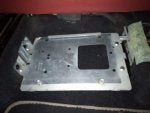
2. Preparing the mounting bracket
Pulling out the pieces of carpet on each side under the left-hand seat.
Install the small bracket 1K0035933 - it sits quite low down (see picture in post above). There are bolts sticking up from the floor that it slots on to - once it's in, fasten in place with the Nylock nuts.
3. Get everything out of the way
Remove the rear seat.
Remove the rear side trim (two T20 screws at the base, one T15 by the seat belt, disconnect the tweeters) and place them where the rear seat was.
Remove the
bonnet release and accompanying panel.
Remove the right-hand side panel in the footwell, which should just pull off.
Remove the
glove box.
Unscrew the panel above the pedals for access.
Remove the kick panels that run along the doors.
Remove the trim around the head unit using a nylon trim tool, then remove the head unit (four T20 screws, then unplug).
4. Wire pulls
Lift up the carpet between the door sill and the left-hand seat, and push a stiff wire through towards the mounting bracket. You will use this to pass wires to and from the amplifier. Note that there is a convenient cut in the sound insulation just where the wires come out. Use this to route wires to the door sill.
Push a stiff wire through the back of the head unit cavity to the left. (Writing from experience of an LHD car, it was hard to get these wires through. If you have an RHD car and can easily pass wires through to the left from the head unit cavity, pass the wire pull to the right instead, and note that you may have to push wires to the right-hand speakers from the head unit cavity, instead of running the wires from the speakers as I have done.)
5. Head unit wiring
Remove any accessory connectors from the quadlock connector. Plug the modified retrofit adapter into the quadlock connector, and install the accessory connectors in to the adapter. Plug in the two ISO harnesses you made. Using the wire pull, pull the CAN-bus wire, the eight woofer wires and the eight audio input wires to the left, and route them safely out of the way of everything to the wire trunk on the left-hand side, along the left-hand door sill, and then use the second wire pull to get them out where the amplifier will go. Crimp 1.5mm terminals on each wire and install them in the plugs.
6. Rear tweeter wiring
Run two 1.0mm2 wires from the left rear tweeter. Run the wire under the seat belt mount, along the door sill and use the wire pull to take it under the seat. Attach a 1J0972712 connector at the tweeter end, then crimp 1.5mm terminals on the amplifier end and install them in the plugs.
Do the same for the right rear tweeter, but running the wire along the right door sill (again, under the seat belt mount), across the dashboard via the head unit cavity, and down the left door sill.
7. Door speaker wiring
The door connector is hidden behind a foam rubber gasket. Remove this gasket to identify the required wire length, then run four 1.0mm2 wires from the left door along the door sill to the amplifier. Crimp male 2.8mm terminals on the door end of each wire, and 1.5mm terminals on the amplifier end. Do the same for the right door, running the wire across the dashboard then along the door sill.
8. Ground terminal wiring
Crimp a 2.8mm female terminal to the 2.5mm2 ground wire, and 1.5mm female terminals to the 1.5mm2 ground wires, and install in the amplifier plugs. Use the wire pull to pull the ground wire from the amplifier side towards the door sill. Run the wire along the door sill, add the eye connector to it, undo the grounding nut by the bonnet release, and fasten the ground terminal.
9. Positive terminal wiring - preparation
Undo the bolt that holds the battery down, taking care not to undo it completely or lose anything in the engine bay, then remove the battery. Remove the rear part of the battery cover and the fuse box cover. Undo the T40 bolt in the middle of the fuse box, then lift it up and to the front of the car. Under the fuse box you will see the rear electronics box. Release the two tabs, and slide the electronics box out to the left (as you look at it standing at the front of the car). Release the purple contact lock by releasing the two small tabs in the centre with a flathead screwdriver, and pushing the large purple lug to the left. Examining the rear of the electronics box, identify terminal 17. Use a pin removal tool from the front to push out the rubber grommet in this terminal, and keep the grommet.
10. Positive terminal wiring
Crimp a 2.8mm female terminal to the 2.5mm2 power wire, and 1.5mm female terminals to the 1.5mm2 power wires, and install in the amplifier plugs. Use the wire pull to pull the positive wire from the amplifier side towards the door sill. Run the wire along the door sill. At the top of the footwell, a bundle of wires disappears into a rubber grommet. Using a stiff pointy object (a Philips screwdriver will do, you heathen), make a hole in the grommet and pass the wire through. In the engine bay, pull the wire through and trim it to length. Make a hole in the grommet you removed in the previous stage and push the wire through it. Crimp the big MCP terminal on to the wire and install it in terminal 17 on the electronics box. Reinstall the electronics box, install the fuse box on top and tighten the T40 screw (you may need to push down on the fuse box, tighten, and repeat a few times to get it completely in). Put a 30A fuse in location 18.
11. Mounting the amplifier
To mount the amplifier, put the plastic retaining lugs into the holes on the centre console side of the footwell, put the amplifier plate in place, and fasten it to the mounting bracket using the M6x10 bolts and into the plastic retaining lugs on the other side with the 4.8x17 screws. Connect the two plugs to the amplifier, then slot it into the bracket. Fasten with the two screws that hopefully came with your mounting bracket (if your mounting bracket didn't come with screws, maybe M6x10 bolts would work?) and install the cover.
12. Rear speakers
I already installed the Dynaudio speakers. If you didn't, please refer to my
guide, disregarding anything about crossovers. Plug the woofers into the existing connections, and the tweeters into the new cables that you ran for them. When installing the tweeters, note that a hot melt glue gun may not suffice - you may wish to fasten them additionally with cloth tape.


")